
Stylized Water 3

4.8.River mode

By default, the water effects will flow in the direction configured under the “General” tab. Some effects like normals and foam have a secondary layer that flows in the opposite direction.
For rivers/creeks, the water should always appear to flow in a single direction. A water material can be configured to behave in such a way!
Material setup
First, and foremost, enable the “River mode” material option.
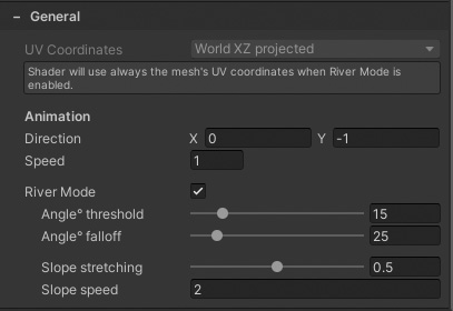
When enabled:
- Texture coordinate are forced to use the mesh’s UV channel. In the context of a spline mesh, this means the water can appear to flow along its curvature.
- A slope factor is calculated, based on the configured angle and falloff.
- Surface Foam is also drawn on slopes, and gradually becomes less visible as the water flattens out. A “Slope Foam” parameter becomes available to control this.
- A separate normal map texture can be used, visible only on slopes.
Be sure to assign a normal map in the now available “slopes” slot:
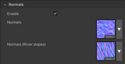
This texture sample uses the sample coordinates/speed as the regular normal map, but it only becomes visible on slopes.
Similarly, when the Surface Foam feature is enabled you can specify how much foam is added to slopes.
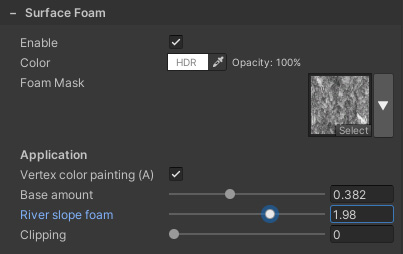
For both Normals and Surface foam, you must ensure that any Speed values aren’t negative (which they are for materials used for lakes)
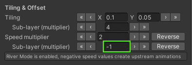
Creating river geometry
Any river material needs a mesh to work with. Typically, river geometry is generated from a spline curve, rarely by hand.
This workflow is a fairly broad subject, and this asset doesn’t contain any functionality to achieve this, since it’s simply not a modeling tool asset.
For example, River Auto Material, EasyRoads3D or Spline Mesher could be utilized to create spline meshes inside the editor. Though the shader will not support RAM’s flowmap painting functionality. But basically any spline tool that can tile a quad mesh will do.
River geometry could also be created in external 3D modeling software (eg. Maya or Blender), but this workflow is not nearly as intuitive as using tools right inside Unity.
Mesh requirements:
- UV shells are laid out straight, without any overlapping shells (necessary for seamless texture tiling)
- Black vertex colors (so nothing interferes with vertex color controlled shading functions). Most modeling software default to white vertex colors (RGBA: (1,1,1,1)).
Caveats:
- The mesh needs vertex normals, which is highly conventional anyway (otherwise slope calculates fail, as do many shading features).
- When using normal maps, the mesh requires tangents need to be calculated (eg. Mesh.RecalculateTangents)
The Bezier Path Creator (now deprecated) asset is an exception that doesn’t meet these requirements, resulting in odd-looking shading.
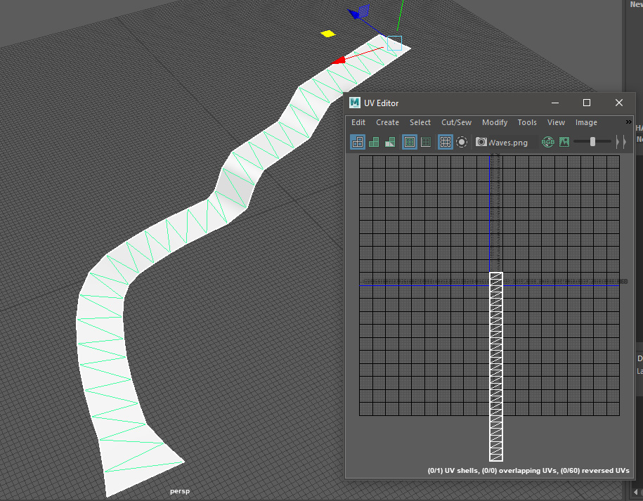
Correct: UV laid out vertically, creating continuous repeating UV coordinates
If the spline geometry isn’t generated/modeled with a continuous UV, you’ll notice a discontinuity in the textures, visible as a seam. It’s likely any spline mesh tool offers a UV tiling parameter. Ensure this is set to a rounded value (eg. 1, 2, 3, etc).
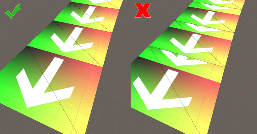
Left: Correct UV tiling. Right: no so much
Should the water flow in the opposite direction (upstream), you can use a negative Y-direction on the material to mitigate this. Though this indicates you should actually flip your UV map vertically.
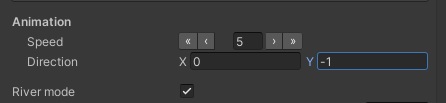
Instead, ensure the UV map of the mesh has a correct rotation to begin with.
The spline tool rotates the UV coordinates by default, this option must be disabled under “UV Settings”!
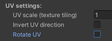
Blending rivers with lakes
This is fairly straightforward to achieve. Essentially, you want the last bit of the river geometry to fade out as it starts to touch the water body. The opacity of the material can be controlled through Vertex Colors, which makes this possible.
First, ensure the river material always draws over the other (receiving) water material, by modifying the render queue on the river material to 3001 (transparent queue + 1).
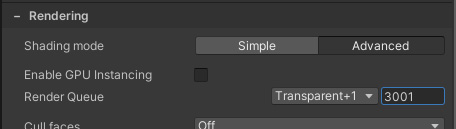
The ZWrite option must also be enabled on the (receiving) water material.
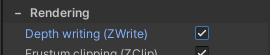
Secondly, enable the use of vertex colors for transparency on the river material.

The Green vertex color channel can now be used to make parts of the mesh completely transparent. See the Vertex Colors section for more details. You’d want to paint the end of the river mesh, that touches the lake, so it appears to blend in with it. Some spline tools may offer control over vertex colors per node/knot, which works just as well.
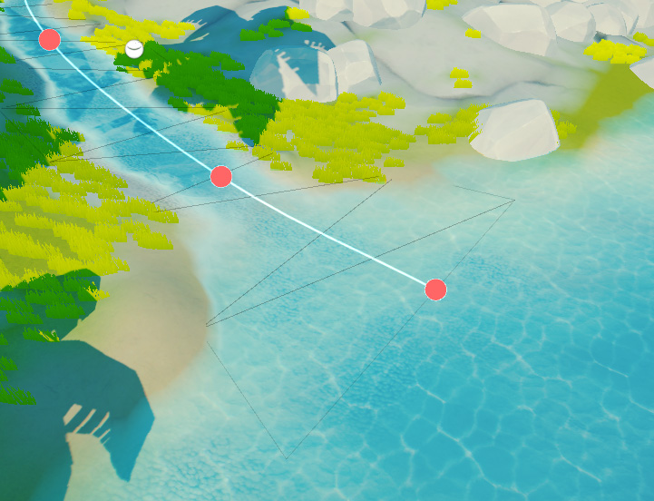
End part of the spline mesh having green vertex colors, making it fade out
 Was this helpful?